https://en.wikipedia.org/wiki/E_series_of_preferred_numbers#...
The fact of the matter is that nowadays, E96 series resistors are readily available and dirt cheap. And if you need more precision than that, you either don't know much about electronics or you know a whole lot about electronics, heh.
Going within 0.1% of an E12 value is a pricey resistor, but resistors that are matched nearly perfectly and are 2-3% off are cheap and easy to find.
In any case, the above trick is neat, thanks for sharing it.
Hell, I don’t even think all of E12 is necessary. I’ll stick to E6 most of the time.
Sense resistor? 0.1 ohm.
Resistor for an LED: 100 ohm
Pull up resistor: 10k
Bias resistor for some mosfet gate: 10M
Voltage divider to measure the battery voltage with an ADC: two 100k resistors.
It's super rare I need anything else. I hate fiddling about with switching the reels on the pick'n'place anyway.
edit: Actually, I'm not so sure anymore that the tolerances would add up in series... I should probably just look this stuff up, since I'm not awake enough to intuit correctly, I think.
In general, however, it's much better to measure/sense physical phenomenon by first converting it into frequency, because it is much easier to measure frequency precisely. Using something like a TCXO from Seiko Epson with 1 ppm tolerance, and measuring over time, you can easily achieve 0.00001% precision and beyond. I know that strain gauges used in civil engineering often utilize this concept, where a metal string is "plucked" electronically and the frequency is then measured.
[0] https://www.vishay.com/docs/61010/ccc.pdf and https://foilresistors.com/docs/63120/hzseries.pdf
If I call correctly, TAoE said engineering calculations should never keep too many significant digits, since no real-world components are that accurate, and all good designs should keep component tolerance in mind - they should not have an unrealistic expectation of precision. It also mentioned that designing a circuit for absolute worst-case tolerance is often a waste of time.
But I don't think TAoE told you to "avoid precision components in your design, use trimmers instead" (Do you have a page number?) when the application calls for it. For example, 0.1% feedback resistors in precision voltage references are often reasonable.
> For high precision one can use trim potentiometers
From what I've read (from other sources), mechanical trimmer used to be extremely popular, but they went out of favor in recent decades because tuning could not be automated and that increased assembly cost. Using a 0.1% resistor is favorable if it allows trim-free production.
> or maybe even digital potentiometer with an ADC at the other side to measure and get as close as possible
Yes, digital trimming and calibrations is today's go-to solution.
Also, component-level precision has limits because eventually trace impedance starts to be significant (hence the use of trim components you mentioned!).
Youtuber Marco Reps goes through various high precision equipment that often have precision resistors and such, recommended if interested!
I've done stuff that needs high precision resistors, but usually the specific value isn't that important, just that it's a known repeatable value.
But yeah, for digital signals, oft times 1k or 100k make no difference.
My intro circuit analysis prof gave these wise words to live by: “If you need more than one significant digit, it isn’t electrical engineering, its physics”
Neither.
Let R_{1, ideal}, R_{2, ideal} be the "ideal" resistances; both with the same tolerance t (in your example t = 0.05).
This means that the real resistances R_{1, real}, R_{2, real} satisfy
(1-t) R_{1, ideal} ≤ R_{1, real} ≤ (1+t) R_{1, ideal}
(1-t) R_{2, ideal} ≤ R_{2, real} ≤ (1+t) R_{2, ideal}
Adding these inequalities yields
(1-t) (R_{1, ideal} + R_{2, ideal}) ≤ R_{1, real} + R_{2, real} ≤ (1+t) (R_{1, ideal} + R_{2, ideal})
So connecting two resistors with identical tolerance in series simply keeps the tolerance identical.
reference: https://people.umass.edu/phys286/Propagating_uncertainty.pdf
disclaimer: it will be a relatively small effect for just two resitors
aleph's comment is also correct. the bounds they quote are a "wost-case" bound that is useful enough for real world applications. typically, you won't be connecting a sufficiently large number of resistors in series for this technicality to be useful enough for the additional work it causes.
To give an example, let's say you've got two resistors of 100 Ohm +/- 5%. That means each is actually 95-105 Ohm. Two of them is 190-210 Ohm. Still only a 5% variance from 200 Ohm.
So are the 68 Ohm and 75 Ohm.
I'd better spell-check this comment before clicking reply...
> […] Continuing this trend, rounding as needed, and we end up with the series 10, 15, 22, 33, 47, and 68. Components built to the E6 standard have a 20% relative error tolerance, and if we look at the values again we’ll see a trend. Starting with 10 again and adding 20% error we end up with 12. Moving to 15 and subtracting 20% we get… wait for it… 12. Moving up from 15 we get 15 + 20% = 18 and 22 – 20% = 17.6. This trend repeats no matter what range of powers of 10 you use, as long as they are consecutive. So 47kΩ + 20% = 56400, while 68kΩ – 20% = 54400.
> Look again at the values 47 and 68. The max/min values overlap right about 56, don’t they? That sounds familiar. The E12 standard uses all of the same values as E6, but with 6 more values mixed in. These 6 additional values are roughly where the E6 values overlap, and now in order to cover the entire range our %-error is reduced to 10%. Starting again at 10, we have 10, 12, 15, 18, 22, 27, 33, 39, 47, 56, 68, and 82. The math holds true here as well, with the error values just slightly overlapping.
It's the 'tolerance overlap' concept that makes the numbers work, but I don't think I've ever seen it explained so clearly before.
This only works with perfect resistors, though. If your actual resistors have a fabrication tolerance, you might be more off. For example, if you need a 41 Ohm resistor, you can use a perfect 47 Ohm resistor from the E6-series, and you'll be within 20% error. However, if that 47 Ohm resistor has a 10% fabrication tolerance, in reality it might be 51 Ohm, and that's more than 20% off from the 41 Ohm you needed.
To take the example from the author's last paragraph, if you need a 70 Ohm resistor, the idea is not that you could be lucky and find an exact 70 Ohm in your E24 resistor set, but that you change the design to use a 68 Ohm instead, and don't introduce more than 5% off by doing so (regardless of the resistor value you needed).
He says about the cables:
> Each size of cable had a max/min rating that just overlapped it’s neighbor above and below, so every required value was covered by one or more cable.
So that means if you needed a "size 12" cable you could pick a size 10 OR a size 15, and they would both work.
But if you need a 12ohm resistor, it's possible that neither the 10 nor the 15 might work, because the 10 could be a 9 and the 15 could be a 17. So I don't really see how it connects.
To put it another way, what if we had 1000% error tolerances? Could we then get away with just a 1ohm. 1000ohm and 1Mohm resistors, because their tolerances overlap? Obviously not, so I don't see how it relates.
Also each resistor is a range, not a single value, since each resistor changes value with temperature & other environmental factors (though temperature is the biggest). That variation is (for normal resistors) less than the tolerance range.
https://digilent.com/blog/wp-content/uploads/2015/01/E12_ser...
Like yes, this means that if your manufacturing tolerances are typically some percentage of the amount (more natural than an additive error) then the overlaps are nicely spaced. But a log scale means that's true for any relative allowance (manufacturing or otherwise), which is the much more natural sort. It doesn't matter if your 100-foot house is off by 1mm, but it does matter if your 1mm-thickness fork is.
Except that it is the tolerance overlap that allows for that specific distribution to work.
For me, that means that my 0402s are all 1/16W, 0805 are 1/8W, 1206 1/4W, etc. And all of my through-hole resistors are 1/4, because the wire stock plays well with breadboards better.
There are probably 1/4W 0402s out there, but that's definitely a specialty piece. I'm seeing 16 cents a resistor/each for a 1 MOhm 1/4W 0402, which is about 4 times what I'd expect to pay for a 1/16W of the same resistance and package.
https://www.digikey.com/en/products/detail/yageo/PA0402CRF5P...
But to your point, Digikey has >70,000 0402s in 1/16W. There are 900 rated for 0.05W, and they're all exotic high-frequency/low temp coefficient/high-precision specialty parts.
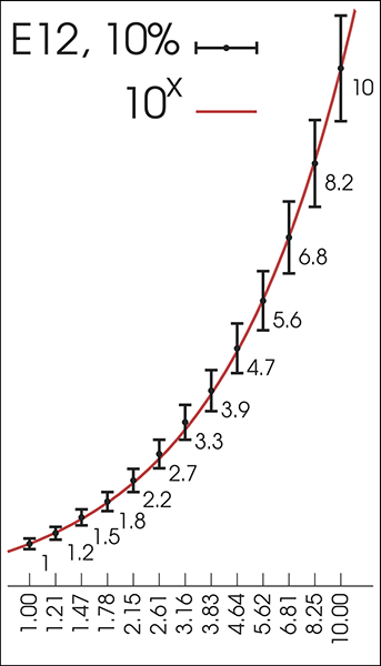
The caption on the graph (and the paragraph before the graph) directly addresses this: "This graph shows how any value between 1 and 10 is within ±10% of an E12 series value, and its difference from the ideal value in a geometric sequence."
> We have to go back a few years to 1877 France. The French military used balloons for various purposes and of various sizes, and they had to be anchored using cables. Over time, they ended up with 425 different sizes of mooring cables that had to be individually ordered and inventoried. Talk about a nightmare. > > Enter Charles Renard. He was tasked with improving the balloons, but discovered this rat’s nest of cables in the inventory closet instead. He spent some time thinking about it and came up with a series of 17 cable sizes that would allow for every type of balloon to be properly moored.
I'm astonished that 425 distinct mooring-cable sizes were ever allowed to happen, and I'm also slightly astonished that even the cleaned-up version used 17. Anyone have more info about that? What were they doing with all those different-sized ropes? How many different balloon models could there have been?
I suppose that makes sense, though it still seems weird that they needed that many types.
It quickly calculates pairs of resistors from E12 (and other) resistor series to meet a target.
Yellow and Purple striped critters inside of HeathKits.