I don't have the patience to reverse-engineer these types of boards, but I do find them really interesting to think about. CAD was just getting started (I just looked up that Gerber format was released in 1980) so I wonder if the masks were hand-drawn.
That's what I was curious about - otherwise there would be effectively be through-vias along the traces (so traces could be probed between devices.)
The claim is multi-layer, but I seriously doubt that. I suspect that these are two-layer boards.
And if that's the case, the pattern is most likely because the holes precede the etch. And possibly precede the copper deposition so that the copper deposition can coat the insides of the holes.
And the holes are in a regular pattern because CNC simply wasn't a thing yet. You probably had some fixed array of drill bits that were used to make the holes in a very strict fixed automation fashion.
I imagine it was a function of the design constraints in that time period, and similar program needs.
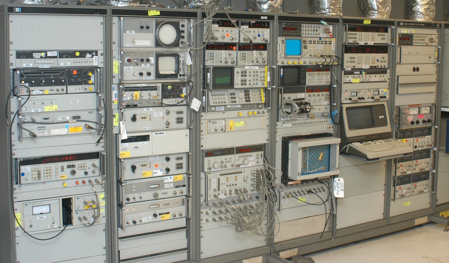
There are very few records of any of this out there, similar to the Spacelab equipment I imagine. The -484 ran a Harris H100 minicomputer with an HP terminal and a GPIB bus. I've linked one of the few photos that you can find, but it's from an extended version of the test bench and has the minicomputer rack off to the right cut off.
Sorry for the off topic, but it's always cool to see stuff like what I spent years working on come across this site!
https://api.army.mil/e2/c/-images/2007/02/12/2612/army.mil-2...